INSTALLATION MANUAL – STOREFRONT DOORS
SD DD-AF DD-AA
SYSTEM DESCRIPTION
- Extruded and filled aluminum framing, tested and approved by UL
- 3-3/8” frame depth
- Clear, fire-rated safety glazing
- Door hardware per shop drawing
REQUIRED TOOLS
- 1/2” open wrench
- Power drill with 3/16” drills
- Heavy-duty glass handling tools
- Non-metal hand wedges
- Gasket roller
- C-clamps
- Metric allen wrench set
- Knife
- Tape measure
- Level
- Rubber mallet
REQUIRED MATERIALS
- Mineral wool insulating material
- Silicone caulking
- ¼” x 3” / 4” zinc-coated flat head sheet metal screws / concrete screws
GENERAL INSTALLATION NOTES
1. Do not drop, roll or drag boxes of aluminum framing. Move and stack boxes with
proper support to prevent distortion. If fork lifts are used, be especially careful about
striking the boxes when lifting or moving.
2. Store in a dry, out of the way area. If rain exposure, condensation or any water
contact is likely, then all packaging material should be removed. Wet packaging
materials will discolor and may stain aluminum finishes and paints.
3. All materials should be checked for quantity and quality upon receipt. Aluflam must
be contacted immediately of any discrepancies in shipment. Check to make sure
that you have the required supplies and tools necessary for the installation.
4. Carefully check the openings and surrounding construction that will receive your
material. Remember, if the construction is not per the construction documents, it is
your responsibility to notify the general contractor in writing. Any discrepancies must
be brought to the general contractor’s attention before you proceed with the
installation.
5. Collect your shop drawings, materials, packing list, and this installation manual.
Carefully review parts location, the sequence of installation, when you glaze it, and
how you seal it. Installation instructions are of a general nature and may not address
every condition you will encounter. The shop drawings were prepared specifically for
the project.
6. Any material substitutions must be of equal or greater quality. Consult Aluflam prior
to substituting any material to ensure that the products’ fire ratings are not violated.
7. Remember to isolate, in an approved manner, all aluminum from uncured masonry
or other incompatible materials.
8. System-to-structure fasteners are not supplied by Aluflam. Fasteners called out on
shop drawings are to indicate minimum sizes.
9. If any questions arise concerning Aluflam products or their installation, contact
Aluflam for clarification before proceeding.
10. Aluflam product installation is frequently completed before drywall, flooring and other
products. Take the extra time to wrap and protect the installed material.
11. Cutting tolerances are ± 1/32”, unless otherwise specified.
12. Aluflam framing products are prefinished and prefabricated, and must be protected
against damage.
13. Concrete, mortar, plaster, muriatic acid and other alkaline and acid based
construction and cleaning materials may be very harmful to door finishes and should
be removed with water and mild soap immediately or permanent damage or staining
of the finishes may occur. A spot test is recommended before any cleaning agent is
used, and abrasive type cleaners must never be used.
14. Doors are never to be used as ladders, step stools, scaffolds or scaffold supports.
15. All work must start from, and be referenced to benchmarks, offset lines and/or
column centerlines established by the architectural drawings and the general
contractor.
16. All doors and frames must be installed plumb, square, level and true, and in
accordance with approved shop drawings.
17. Glass and glazing building codes governing the design and use of products vary
widely. Aluflam North America, LLC does not control the selection of the products,
product configurations, operating hardware and function, or glazing materials, and
Aluflam assumes no responsibility for these design considerations. It is the
responsibility of the design professional, owner, architect, specifier, general
contractor, and the installer to make these selections in strict accordance with all
applicable codes.
INSTALLATION
STEP 1
DETERMINE DOOR FRAME REFERENCE POINT
Establish the door frame reference lines or the exterior/interior plane of the doors to be
installed using either bench marks, offset lines, or column centerlines provided by the
general contractor and referenced on the shop drawings. Use the established reference
points to determine the installation points for each door frame opening at the head, and
jambs.
STEP 2
UNPACK DOORS AND FRAME
The Aluflam door systems are packaged for freight with the doors installed in the frame.
a. Without removing the door frames from the freight container, carefully open door
leaf 90° and remove from the hinges by sliding leaf toward top of frame.
b. Set the door leaf aside in a well protected area, especially assuring that
protruding trim hardware is well protected.
c. Remove other loose materials, such as glazing beads, intumescent strips, seals,
etc, and set aside in a well protected area.
d. Carefully lift frame out of packaging. At this point, the frame joints are
unprotected. Handle the frame with extreme care to avoid separation of corner
joints.
STEP 3
MULTIPLE FRAMES
a. In the case of attached, multiple frames – assemble the frames prior to installing
into the wall opening. See Figure: Typical Frame-to-Frame Joint Detail.
b. Lay out all frames to be attached on a smooth, dry surface. Ensure that frames
are well protected from abrasion and impact. Strips of wood are very suitable for
this purpose.
c. Insert frame splines (2 per joint) into narrow groove on outside edge of frame to
be joined. Splines may be lubricated with liquid soap for ease of insertion.
Assure that frames line up length-wise and secure using c-clamps.
d. Anchor joints through factory pre-drilled holes.
STEP 4
INSTALLATION OF FRAME
a. Detach wood/metal strip connected to lower end of frame.
b. Install the frame plumb, square, level and true.
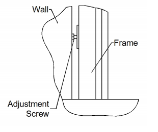
c. Gradually and evenly back out all adjustment screws with ½” open wrench (see
detail). Be careful to not cause frame distortion due to excessive adjustment.
d. Measure the size of the frame and ensure that it meets the dimensions
referenced on the shop drawing.
e. Drill anchor locations into
surrounding structure using the
factory pre-drilled frame holes as
guides. Use 3/16” drill.
f. Anchor the frame to the wall
opening at all pre-drilled anchor
locations.
g. Ensure that frame dimensions
have not changed.
STEP 5
INSTALLATION OF DOOR LEAF
a. Install door leaf by aligning the
hinges and lowering the leaf intob. Install setting blocks between glass unit
and steel angle brackets at locations 2, 3,
and 4. If necessary, use non-metallic
prybar to slightly shift glass position.
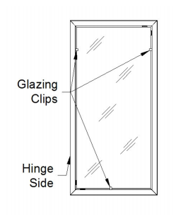
c. While supporting glass in place, secure it
by manually bending stainless steel
glazing clips in three locations (see
figure).
d. Proper corner blocking of the glass is key
to the performance of the door. Carefully
operate door leaf to assure that it opens
and closes freely. If necessary, adjust
door clearances by adjusting blocking of
glass units and/or adjusting the hinges
(see separate hinge instructions).
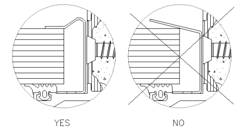
e. Permanently fix the glass unit by bending
remaining stainless steel glazing clips.
See illustration below. (DO NOT USE
METAL TOOLS)
f. Snap in glazing beads on all four sides of leaf. If necessary, use mallet or other
non-metal tool to force glazing beads into place.
g. Install glazing gaskets.
position
b. Assure that the door leaf swings freely and that it opens and closes without
interference.
STEP 6
PREPARE FOR GLAZING
Aluflam doors require “Corner Blocking” for
proper operation.
a. Inspect the factory installed intumescent
glazing tape in the frame opening and
make sure it hasn’t shifted during
installation.
b. Place setting block on top of steel angle
bracket at location 1.
STEP 7
GLAZING
The Swissflam and Contraflam glass products
that are used in Aluflam door systems are heavy
and fragile. Make sure that proper tools and
lifting capacity is available prior to opening glass
crate.
Avoid impact with any metal objects and avoid
setting the glass down directly onto floor. Use wood strips or other suitable material for
setting down the glass section prior to installation.
For full instructions on handling and installing glass, please refer to Vetrotech SaintGobain’s installation instructions.
a. Center the glass in the door leaf and carefully set the unit down onto the setting
block at location 1.
STEP 8
HARDWARE
a. Attach door closers and other remaining hardware per shop drawing and
hardware installation instructions.
STEP 9
FINISHING
a. Fill gaps around frame with mineral wool insulating material. Pack as tightly as
possible.
b. Finish gaps by applying a continuous bead of silicone caulking.
c. Clean glass units using mild glass cleaner. For further information, refer to
Vetrotech’s glass cleaning and maintenance instructions.
STEP 10
ADJUSTMENTS
For adjustments to hinges, doorclosers, and other hardware – please refer to the
manuals from the hardware manufacturers.


